
In this tutorial we will learn how to make wireless communication between two Arduino boards using the nRF24L01 transceiver modules. The nRF24L01 module is very popular choice for wireless communication when using Arduino.
Table of contents
- Overview
- nRF24L01 Transceiver Module
- How It Works
- Module variations
- nRF24L01 Module Pinout
- How to Connect the nRF24L01 to Arduino
- Arduino and nRF24L01 Code
- Troubleshooting
- Bi-directional Wireless Communication with two NRF24L01 and Arduino
- Example 3 – Sending multiple variables in a single package
- Conclusion
I have already used this module for numerous Arduino projects and you can check out some of them here:

- DIY Arduino RC Transmitter
- Arduino RC Airplane | 100% DIY
- DIY Arduino based RC Hovercraft
- Arduino Wireless Weather Station Project
You can watch the following video or read the written tutorial below. It includes everything we need to know about the nRF24L01 transceiver module, such as the module pinout, working principle, wiring and several code examples.
Overview
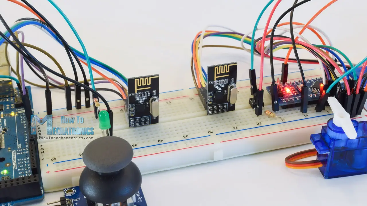
For explaining the wireless communication we will make two examples, the first one will be sending a simple “Hello World” message from one Arduino to another, and in the second example we will have a bi-directional communication between the Arduino boards, where using the Joystick at the first Arduino we will control the servo motor at the second Arduino, and vice versa, using the push button at the second Arduino we will control the LED at the first Arduino.
nRF24L01 Transceiver Module
Let’s take a closer look at the NRF24L01 transceiver module. It uses the 2.4 GHz band and it can operate with baud rates from 250 kbps up to 2 Mbps. If used in open space and with lower baud rate its range can reach up to 100 meters.

Here are complete specifications:
| Frequency range | 2.4 – 2.5GHz ISM band |
| Data rates | 250Kbps / 1Mbps / 2Mbps |
| Max. output power | 0dBm |
| Operating voltage | 1.9 – 3.6V |
| Max. operating current | 12.3mA |
| Standby current | 22µA |
| Logic inputs | 5V tolerant |
| Communication range | 100m (open space) |
How It Works
The module can use 125 different channels which gives a possibility to have a network of 125 independently working modems in one place. Each channel can have up to 6 addresses, or each unit can communicate with up to 6 other units at the same time.

The power consumption of this module is just around 12mA during transmission, which is even lower than a single LED. The operating voltage of the module is from 1.9 to 3.6V, but the good thing is that the other pins tolerate 5V logic, so we can easily connect it to an Arduino without using any logic level converters.

Three of these pins are for the SPI communication and they need to be connected to the SPI pins of the Arduino, but note that each Arduino board has different SPI pins. The pins CSN and CE can be connected to any digital pin of the Arduino board and they are used for setting the module in standby or active mode, as well as for switching between transmit or command mode. The last pin is an interrupt pin which doesn’t have to be used.
Module variations
There are several variations of the NRF24L01 modules. The most popular is the one with on-board antenna. This makes the module to be more compact, but on the other hand, lowers the transmission range to a distance of about 100 meters.
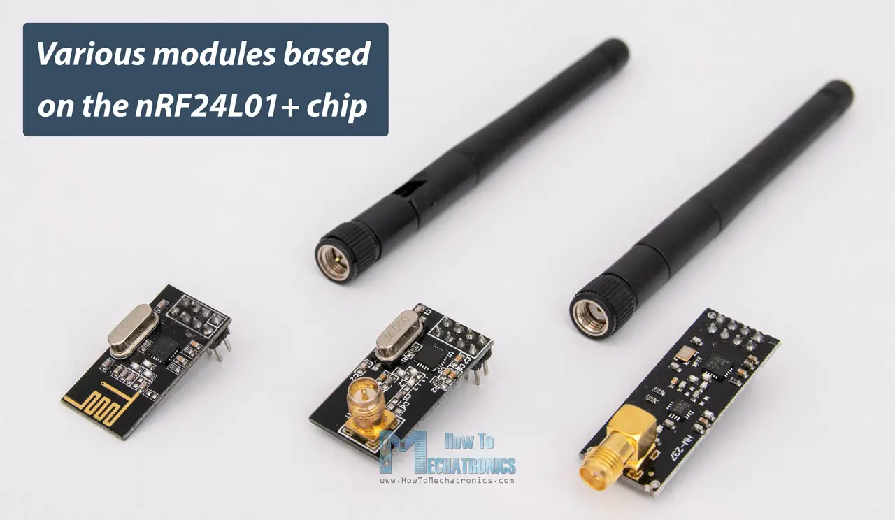
The second variation, instead of on-board antenna, it has a SMA connector and which we can attach a duck antenna for better transmission range.
The third variation shown here, in addition to the duck antenna, it has a RFX2401C chip which includes PA (Power Amplifier) and LNA (Low-Noise Amplifier). This amplifies the NRF24L01 signal and enables even better transmission range of up to 1000 meters in open space.
nRF24L01 Module Pinout
Here’s a detailed look at the NRF24L01 pinout, as well as the NRF24L01+ PA/LNA module.
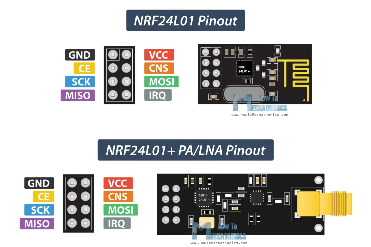
Both modules, the NRF24L01 and the NRF24L01+ PA/LNA have the same pinout, so we can connect them in our circuit the same way.
How to Connect the nRF24L01 to Arduino
Here’s how we need to connect the NRF24L01 modules to the Arduino boards.
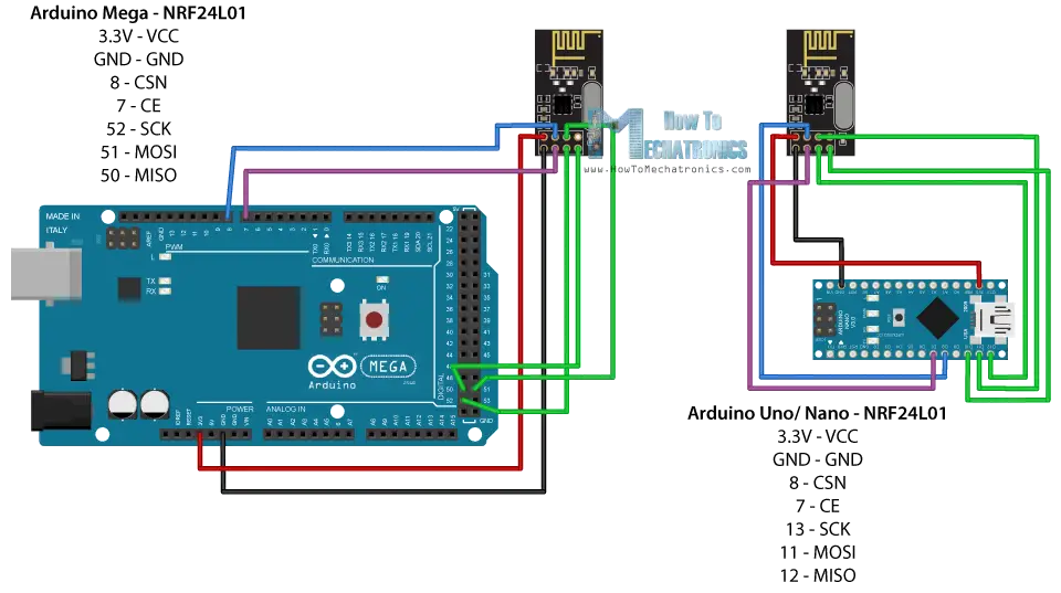
As I already mentioned, each Arduino board has different SPI pins, so keep that in mind when connecting the modules to your Arduino board.
| Arduino | SCK | MISO | MOSI | SS |
| Uno | 13 | 12 | 11 | 10 |
| Nano | 13 | 12 | 11 | 10 |
| Mega | 52 | 50 | 51 | 53 |
SPI pins on different Arduino boards
You can get the components needed for this Arduino tutorial from the links below:
- NRF24L01 Transceiver Module……… Amazon / Temu / Aliexpress
- Arduino Board ……………………………… Amazon / Temu / Aliexpress
- Breadboard and Jump Wires ………… Amazon / Temu / Aliexpress
Disclosure: These are affiliate links. As an Amazon Associate I earn from qualifying purchases.
Arduino and nRF24L01 Code
Once we connect the NRF24L01 modules to the Arduino boards we are ready to make the codes for both the transmitter and the receiver.
First we need to download and install the RF24 library which makes the programming less difficult. We can also install this library directly from the Arduino IDE Library Manager. Just search for “rf24” and find and install the one by “TMRh20, Avamander”.
Here are the two codes for the wireless communication and below is the description of them.
Receiver Code
Code Description
So we need to include the basic SPI and the newly installed RF24 libraries and create an RF24 object. The two arguments here are the CSN and CE pins.
Next we need to create a byte array which will represent the address, or the so called pipe through which the two modules will communicate.
We can change the value of this address to any 5 letter string and this enables to choose to which receiver we will talk, so in our case we will have the same address at both the receiver and the transmitter.
In the setup section we need to initialize the radio object and using the radio.openWritingPipe() function we set the address of the receiver to which we will send data, the 5 letter string we previously set.
On the other side, at the receiver, using the radio.setReadingPipe() function we set the same address and in that way we enable the communication between the two modules.
By using the “&” before the variable name we actually set an indicating of the variable that stores the data that we want to be sent and using the second argument we set the number of bytes that we want to take from that variable. In this case the sizeof() function gets all bytes of the strings “text”. At the end of the program we will add 1 second delay.
Using the radio.write() function we can send maximum of 32 bytes at a time.
On the other side, at the receiver, in the loop section using the radio.available() function we check whether there is data to be received. If that’s true, first we create an array of 32 elements, called “text”, in which we will save the incoming data.
Using the radion.read() function we read and store the data into the “text” variable. At the end we just print text on the serial monitor. So once we upload both programs, we can run the serial monitor at the receiver and we will notice the message “Hello World” gets printed each second.
Troubleshooting
It’s worth noting that power supply noise is one of the most common issues people experience when trying to make successful communication with the NRF24L01 modules. Generally, RF circuits or radio frequency signals are sensitive to power supply noise. Therefore, it’s always a good idea to include a decoupling capacitor across the power supply line. The capacitor can be anything from 10uF to 100uF.
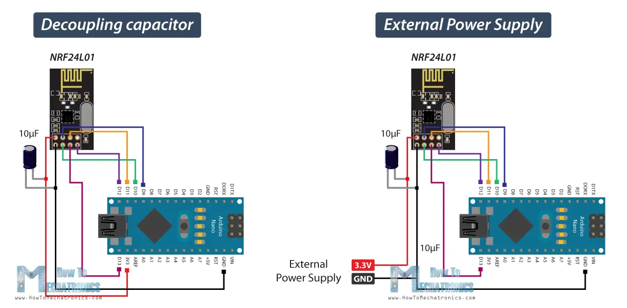
Another common issue is that the 3.3V pin of the Arduino boards, cannot always supply enough power to the NRF24L01 module. So, powering the module with an external power source is also a good idea.